
Introduction
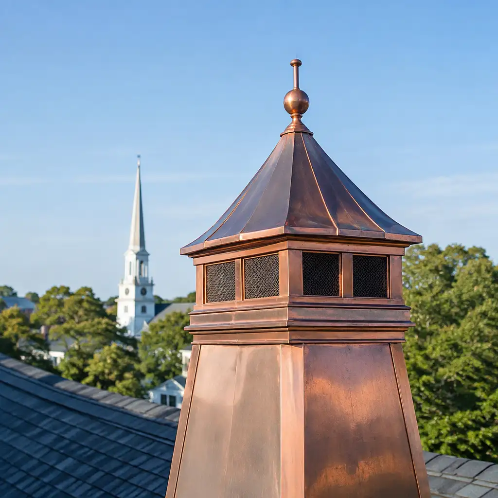
Historic churches in Southeastern Massachusetts and coastal New England present a unique set of challenges when specifying copper chimney caps and louvers. Large ecclesiastical roofs require significant ventilation to control moisture and preserve interiors while simultaneously needing robust weather protection against driving salt spray, wind-driven rain, and avian or insect ingress. For roofing contractors, architects, and preservation specialists, the design choices around copper chimney caps influence long-term durability and the visual integrity of a restored building.
This article provides specification-focused guidance intended for trade professionals: practical design priorities, material selection, salt-corrosion mitigation, airflow sizing, fabrication tolerances, and detailed mounting and flashing recommendations. The recommendations reflect real-world fabrication and installation considerations common across Massachusetts and New England restorations and are grounded in architectural sheet metal practice.
Cape Cod Copper is a family-owned, trade-only copper fabricator that partners with roofing contractors and suppliers on historic restoration and custom projects. For questions about shop tolerances, custom details, or drawing-based fabrication, visit the Cape Cod Copper site to learn how a precision trade partner can support your project.
- Introduction
- Design priorities for historic church roofs in coastal New England
- Selecting copper chimney caps and louvers to resist salt corrosion
- Balancing ventilation requirements with weather protection
- Louver geometry, free area, and airflow sizing for large ecclesiastical roofs
- Fabrication tolerances, materials, and finish options for durability
- Mounting details, flashing integration, and maintenance access
- Frequently Asked Questions
Design priorities for historic church roofs in coastal New England
Begin any specification by defining performance priorities: protect interior spaces from water and salt while enabling appropriate ventilation rates for large volumes. Churches commonly have long roof runs, vaulted ceilings, tall attics, and multiple flues. The chimney cap assembly should address three primary functions simultaneously: prevent bulk water and salt intrusion, exclude pests and debris, and provide the net free area required for mechanical or passive ventilation strategies.
Maintain visual compatibility with historic character. Copper offers an authentic aesthetic and long service life when detailed correctly; however, construction details that look right and perform are critical. Coordinate cap profiles, projection, and patina expectations with preservation architects early in the design phase. When working with a trade-only fabrication partner, provide measured drawings or field dimensions so components are shaped to fit existing masonry and roof geometry.
Assess site exposure. Churches on Cape Cod or the Southcoast of Massachusetts face elevated chloride exposure; details that work inland may fail on exposed towers. Incorporate robust drainage, stainless-steel meshes, and physical separation of dissimilar metals in the specification to limit accelerated corrosion and galvanic activity.
Selecting copper chimney caps and louvers to resist salt corrosion
Copper performs well in many environments, but coastal salt spray increases surface corrosion rates and can trap salts in recessed profiles. For chimney caps and louvers on coastal churches, specify heavier gauges and keep salt retention to a minimum. Recommended gauges for exposed cap housings are 20 oz (0.81 mm) or 24 oz (0.99 mm) copper; these gauges increase resistance to deformation and extend service life in salt-laden atmospheres.
Use stainless-steel bird and insect screens—preferably 316 stainless—instead of bronze or galvanized mesh. 316 stainless resists pitting in marine exposures and avoids galvanic incompatibility with copper when specified with an insulating separation (e.g., non-conductive washers or neoprene gaskets) at fasteners. Avoid installing copper mesh that can trap chlorides; stainless mesh with open area sized for airflow is preferred.
Design cap geometries to shed and drain rather than trap water and salts. Include drip edges, collection gutters inside the cap base, and accessible weep points sized to 3/8″ minimum. If a protective coating is required for aesthetic reasons, specify factory-applied, breathable coatings only after consulting the fabricator—coatings change long-term patination behavior and can complicate repair or soldering in the field.
Balancing ventilation requirements with weather protection
Ventilation and weather protection are often opposing demands: louvers must offer net free area for airflow while presenting an effective barrier to wind-driven rain. Start by establishing actual ventilation needs—passive or mechanical—expressed in net free area (NFA) or cubic feet per minute (CFM). For large ecclesiastical roofs, ventilation targets should be coordinated with the mechanical engineer or building envelope consultant to account for roof area, historic insulation, and interior humidity loads.
When specifying copper louvers used as intake or exhaust at high elevations, choose baffle-style louvers with offset blade geometry rather than straight-perforation panels. Baffle louvers with downward-angled blades (30°–45° face angle) provide substantial rain rejection while maintaining practical free area. Include an internal drainage plane behind the exterior louver to collect and route incidental moisture out through dedicated scupper holes.
Consider separate intake and exhaust strategies to limit water migration into critical interior volumes. Intake louvers should be located low and shielded; exhaust caps placed at ridge or tower summits should have integrated rain hoods and backdraft dampers where appropriate to minimize reverse flow during storms.
Louver geometry, free area, and airflow sizing for large ecclesiastical roofs
Louver sizing is a critical specification item. For passive attic ventilation, the common 1:300 rule (1 square foot of net free area per 300 square feet of attic floor) is a starting point; large vaulted spaces and uninsulated attics commonly require larger allowances or mechanical assistance. For bespoke historic projects, calculate NFA using the building-specific heat and moisture loads or follow the 1:150 rule where higher ventilation rates are needed due to combustion appliances or persistent humidity.
When converting required NFA to louver face area, use the louver’s published free area factor. For copper baffle louvers, expect net free area in the 40–55% range depending on blade geometry. For example, if you need 3 square feet of NFA, specify a louver face area of 6.5–7.5 square feet assuming a 45–50% free area factor and a small allowance for screens and dampers.
Typical copper louver geometry recommendations for church applications:
- Blade projection: 1.25″–1.75″ from face to blade tip.
- Blade opening clearance: 3/4″–1″ nominal between blades to promote drainage and minimize salt accumulation.
- Face angle: 30°–45° downward for optimal rain rejection.
- Free area target: minimum 40% net for intake louvers; increase to 50%+ for exhaust where airflow is critical.
These dimensions are starting points; allow the shop to produce scale mock-ups and free area calculations so the final assembly meets both ventilation and historic appearance goals.
Fabrication tolerances, materials, and finish options for durability
Precision fabrication and realistic tolerances are essential when working to measured masonry and roof dimensions. Cape Cod Copper’s manufacturing capabilities include CNC fabrication and precision forming in 16 oz, 20 oz, and 24 oz copper. Standard tolerance guidance to include in specifications:
- Critical mating faces, flanges, and flashings: ±1/16″ (±1.6 mm)
- Overall assembly dimensions up to 48″: ±1/8″ (±3.2 mm)
- Large assemblies over 48″: ±3/16″ (±4.8 mm)
State any deviation allowances for field-adjustable hems or slip joints that permit a controlled amount of on-site fitting without compromising weather sealing.
Soldering, folded seams, and mechanically seamed joints are all viable depending on access and exposure. Specify continuous soldered seams at exposed vertical transitions where watertightness is required and use solder flux and joint design compatible with lead-coated copper when that material is selected. Lead-coated copper is available when an alternate surface appearance is desired or when matching historic material is required.
Fasteners in coastal projects should be 316 stainless where exposed; for hidden fasteners, 304 stainless is acceptable. Specify non-conductive washers or neoprene isolation pads between copper and stainless steel to reduce the risk of galvanic action at contact points, particularly where salt may be present.
Mounting details, flashing integration, and maintenance access
Proper mounting and integration with roof flashings prevents water migration at the roof penetration. Typical chimney cap base flanges should be sized to a minimum 3″ face where fastened to a counterflashing or pre-existing chase. When mounting to masonry, use stainless-steel anchors sized and spaced to suit wind uplift loads; typical anchor spacing is 6″–8″ on center for small bases and 4″–6″ on center for narrow flanges on exposed towers.
Recommended mounting and flashing details:
- Base flange width: minimum 3″ for a field-soldered or through-fastened connection to flashing or a continuous cradle.
- Saddle/step flashing: fabricate copper step flashings to lap existing chimney flashing by at least 3″ and interleave with mortar joints when required by preservation standards.
- Fasteners: use #10 or #12 316 stainless self-tapping screws with neoprene washers for through-fastened areas; where possible fasten to stainless backing plates inside the flue chase to avoid direct shear on roof tiles or slates.
- Gasket/sealant: specify a non-acidic, permanently elastic sealant at the top face of the base flange for initial weatherproofing; sealant is not a substitute for mechanical waterproofing and should be used only as a secondary barrier.
Design for maintenance. Include removable access panels or soldered seams with provision for desoldering so the cap can be inspected and cleaned. Specify bird-screen access points and internal drainage scuppers with removable strainers; scuppers should be a minimum of 3/8″ diameter and sized to the expected flow with stainless screens to match the exterior mesh material.
Coordinate flashing details with copper roof panels and adjacent roof transitions. Proper interface with standing-seam or slate roofs reduces movement stresses on cap assemblies. For complex transitions, involve the sheet metal contractor early and refer to the roofing panels and flashings product guidance to ensure compatible profiles and attachment methods.
Frequently Asked Questions
Q: What copper gauge is recommended for chimney caps on exposed coastal church towers?
A: For exposed coastal towers, specify 20 oz or 24 oz copper for cap housings and critical flashings. Heavier gauges resist deformation from wind and salt and provide longer service life. Thinner 16 oz copper may be suitable for less-exposed locations or decorative elements but is not recommended for primary weather barriers in high-salt environments.
Q: How do I size louvers to meet ventilation needs for a large vaulted church roof?
A: Start with ventilation targets from the building engineer; use the 1:300 rule for basic passive ventilation or 1:150 for higher needs. Convert required net free area (NFA) to louver face area using the louver’s free-area factor (typically 40%–55% for baffle louvers). Include allowances for screens and dampers when calculating final face dimensions.
Q: What mounting and flashing details reduce water and salt ingress at the roof penetration?
A: Use a minimum 3″ base flange, stainless-steel anchors spaced 6″–8″ o.c. (closer on narrow flanges), continuous counterflashing, and internal drainage scuppers. Specify neoprene or non-conductive isolation at fasteners and provide removable maintenance access. Coordinate with adjacent roof flashings and the copper roof panel details to ensure a continuous watertight transition.
Working from drawings, field measurements, or a custom detail? Cape Cod Copper partners with trade professionals to fabricate copper components made to fit the job, from custom flashings and roof panels to leader heads, chimney caps, vents, and decorative architectural details. Call (508) 946-1999 or email capecodcopper2@gmail.com to review your project requirements.