
Introduction
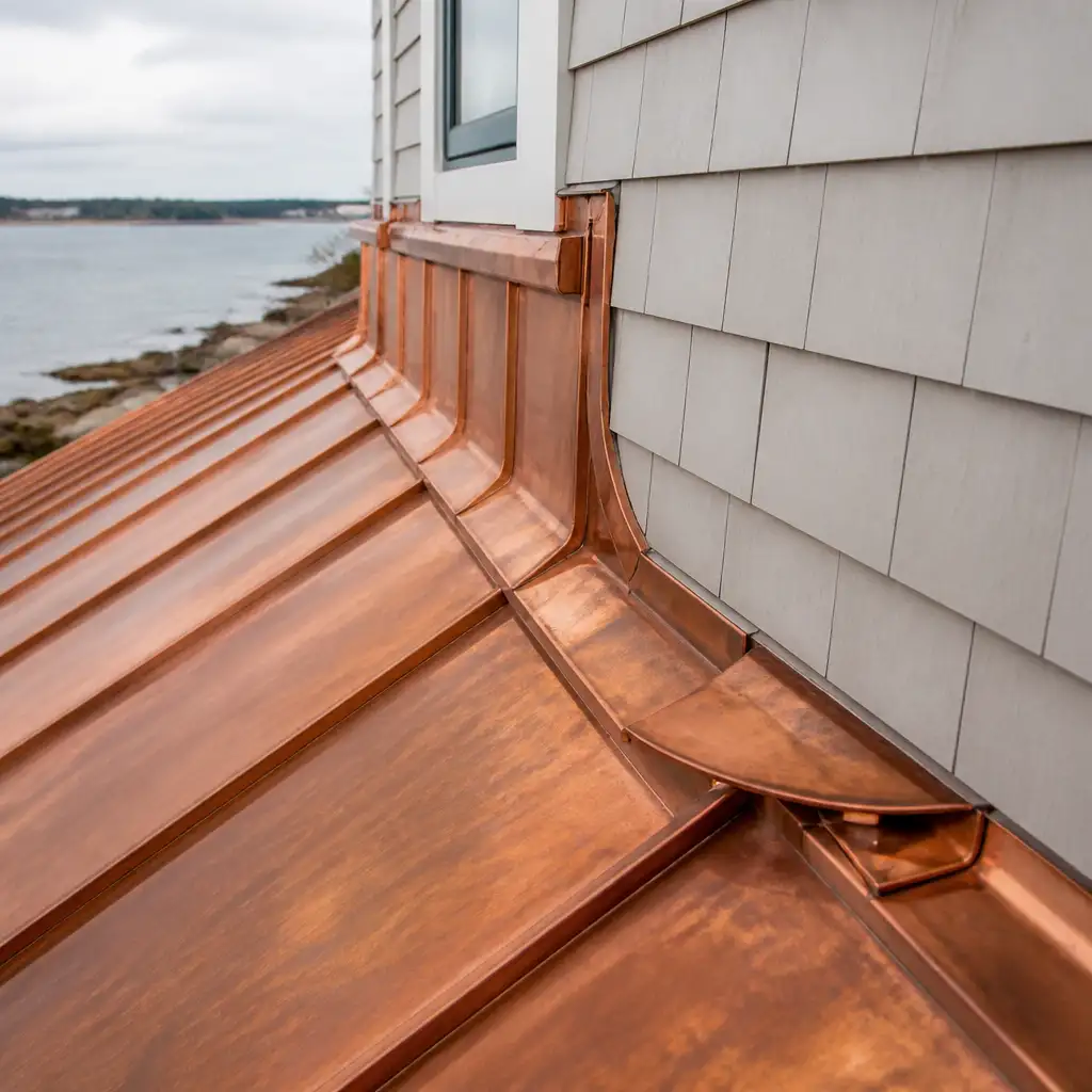
Designing and fabricating copper flashing for roof-to-wall transitions in Southcoast Massachusetts requires attention to shop documentation, precise fabrication tolerances, and close field coordination. This guide on copper flashing Massachusetts is written for roofing contractors, restoration specialists, and architectural metal fabricators working on coastal New England projects.
Coastal conditions on the Southcoast and throughout Southeastern Massachusetts—salt spray, wide temperature swings, and historic cladding assemblies—make proper detailing and durable fabrication essential. Practical decisions made in the shop and on-site determine long-term watertightness and the quality of the visible copper work.
We focus on shop drawing requirements, recommended tolerances, soldering and seam practice, and strategies for integrating flashings with common claddings and complex transitions. The recommendations reflect trade practice, historic restoration concerns, and the fabrication capabilities available from a precision architectural sheet metal shop.
Readers should be professionals: roofing contractors, suppliers, and restoration teams seeking clear guidance to reduce field rework and ensure reliable copper transitions on Massachusetts coastal projects.
- Introduction
- Design fundamentals for roof-to-wall copper flashing
- Shop drawing requirements and fabrication tolerances
- Copper material selection and gauge considerations
- Soldering, seams, and watertight transition techniques
- Field coordination: measurements, templates, and mock-ups
- Integration with cladding and complex architectural transitions
- Frequently Asked Questions
Design fundamentals for roof-to-wall copper flashing
Start with the building control lines and the intended drainage flow. Roof-to-wall flashing should prioritize positive drainage and proper laps above the roof surface. On Southcoast projects, specify fall and slope where possible so standing water is avoided at transitions that drain toward cladding or masonry.
Establish clear lap lengths and anchorage. Typical lap lengths for exposed flashings are 3″ minimum for laps on vertical surfaces and 4″ on horizontal surfaces subject to wind-driven rain, but adjust per project severity and exposure. Prevent water tracking by arranging laps so water always flows over, never under, the next piece.
Coordinate with the roofing panel layout and adjacent roof accessories early. If the project uses standing-seam copper panels or custom copper roof panels, indicate panel seams and fastener lines on the details. For related fabricated components and roof accessories, reference the roofing panels and flashings product category to align flashing details with panel profiles and attachment methods: roofing panels and flashings.
Shop drawing requirements and fabrication tolerances
Shop drawings are the single most effective tool to prevent field issues. Provide dimensioned elevations, plan views, section cuts through the flashing, and notes for tolerances, seams, soldering, and finish. Call out critical dimensions such as overall length, bend locations, and returns to the substrate. Include material gauges and specify whether pieces are pre-formed or field-formed.
State fabrication tolerances explicitly. For architectural copper components produced in a shop environment, use tight dimensional control: +/-1/16″ for critical widths and mating edges, +/-1/8″ for formed lengths over 6′, and radius tolerances of +/-1/8″ where fit is critical. Reasonable bends and hems should be noted with allowable springback and factory bend allowance to minimize on-site adjustments.
Include match-marking and installation orientation on drawings. Number assemblies and indicate which pieces are to be welded, seamed, or soldered. Clear shop notes reduce questions during installation and shorten the field mock-up cycle—important on coastal projects where access windows and tide schedules can constrain work.
Copper material selection and gauge considerations
Select the copper gauge based on exposure, expected foot traffic, roof slope, and historical accuracy for restoration work. Common architectural gauges offered for coastal New England projects include 16 oz (0.0216″), 20 oz, and 24 oz copper. Heavier gauges are advisable for low-slope transitions, parapet caps, and areas with mechanical stresses.
Consider lead-coated copper where specified for enhanced solderability at mortar joints or where direct masonry contact occurs. Material choice should account for allowed fabrication methods—some gauges require different roll-forming and bending techniques and may alter recommended seam types.
Specify finish and patina expectations. Whether pieces are to be shipped mill finish for natural patination or pre-patinated to match an existing roof, call out finish in shop drawings. Fabricators with CNC and precision forming capabilities can reliably produce large or complex pieces in thicker gauges, which is helpful for demanding coastal and historic restoration applications.
Soldering, seams, and watertight transition techniques
Choose seam types by access, exposure, and appearance. Common options include folded locked seams, standing-seam interlocks, and flat laps prepared for solder. For roof-to-wall flashings, a combination of mechanical seaming and soft-soldered lap provides both strength and leak resistance when detailed correctly.
Use back-soldering or continuous fillet solder on horizontal laps to prevent capillary action under the lap. Pre-tinning mating edges in the shop improves capillary flow and reduces field soldering time. Identify solder alloy in the shop notes—many projects accept standard soft solders (lead-containing or lead-free depending on project and code)—and specify fluxes suitable for clean copper joints. Emphasize proper heating technique to avoid overheating the copper and damaging nearby finishes or substrates.
Detail relief and expansion where long runs meet rigid cladding. Include slip joints, expansion crimps, and properly sized reglets or counterflashings to allow thermal movement without stressing seams. In coastal Massachusetts, thermal cycling combined with salt exposure increases the need for accommodation details at long runs and large transitions.
Field coordination: measurements, templates, and mock-ups
Accurate field measurement reduces rework. Use measured templates for complex terminations—corners, curved bays, and irregular masonry returns. When possible, capture templates electronically or submit a requested measurement sheet so the shop can verify dimensions before fabrication starts.
Build a mock-up for complicated transitions. A small, representative mock-up confirms fit, attachment methods, and soldering approach before mass production. Mock-ups are particularly useful for historic restorations and projects with ornate cladding where tolerances are tight and visual match is critical.
Coordinate sequencing with trades. Timing of masonry work, cladding installation, and roofing panel delivery affects flashing strategy. Establish responsibilities for temporary protection, substrate inspection, and final fastening. As a trade-only partner, fabricators can often suggest practical sequencing changes to reduce field callbacks and ensure shop-fabricated pieces fit as intended.
Integration with cladding and complex architectural transitions
Transitions between copper flashing and adjacent cladding—wood shingles, cedar siding, slate, brick, or synthetic panels—demand specific termination details. For masonry, provide through-wall flashing and counterflashing details with appropriate reglet depths and saddle provisions. For wood or composite cladding, use drip edges and cleat systems that allow for movement and drainage behind the flashing.
When flashing meets architectural features such as bay windows, dormers, or decorative cornices, coordinate radius and profile in the shop drawing. A precision shop can pre-form complex profiles to tight tolerances so field adjustments are minor. Indicate required returns, hemmed edges, and concealed fasteners to meet both aesthetic and performance goals.
Document the intersection of flashing with trim and trim accessories. Where flashings connect to gutter systems, leader heads, or chimney caps, call out the connection method and provide dimensions for mating pieces. For assistance with compatible water management components finished in copper, consult the gutters and downspouts product group when designing integrated drainage systems.
Frequently Asked Questions
Q: What shop drawing details are essential for roof-to-wall copper flashing?
A: Include plan and elevation views, section cuts at transitions, material gauge, seam and solder notes, tolerances, match-marking, and installation orientation. Clear lap and anchor details reduce field ambiguity.
Q: Which solder and seam methods work best for coastal projects?
A: Use a combination of mechanical seam locking and soft-soldered fillets or back-soldering for horizontal laps. Pre-tinning in the shop and specifying compatible fluxes help ensure reliable capillary action and long-term watertightness.
Q: How should contractors handle measurement and fit-up for complex transitions?
A: Use measured templates, request mock-ups for critical assemblies, and coordinate sequencing with other trades. Provide the fabricator with clear site measurements and photos so the shop can verify fit before cutting multiple pieces.
Looking for a reliable trade-only copper fabrication partner? Cape Cod Copper works exclusively with roofing contractors, suppliers, builders, and other professional trades, providing quality copper products with craftsmanship, precision, and dependable service. Call (508) 946-1999 or email capecodcopper2@gmail.com to get started.