
Introduction
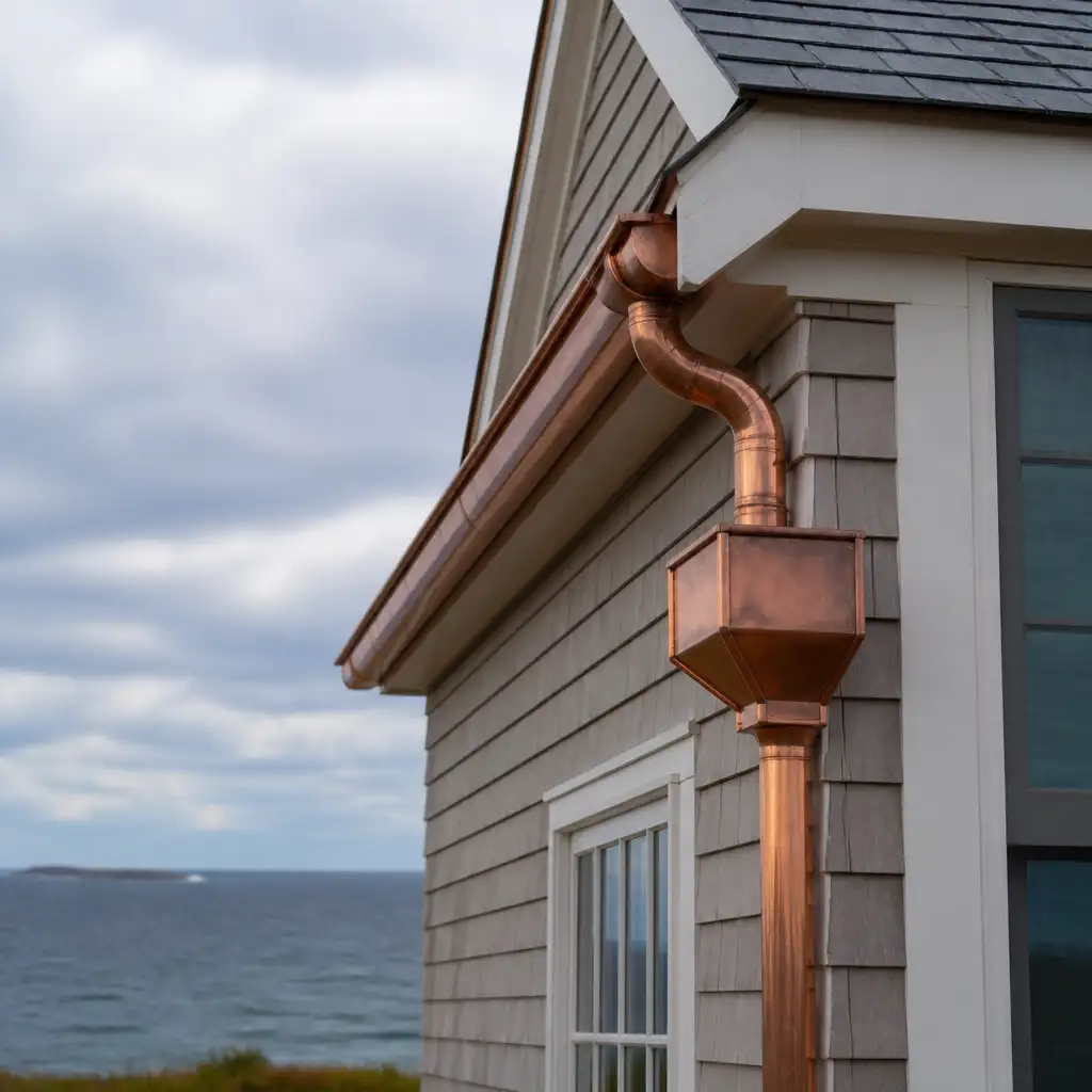
Copper leader heads are a critical junction in roof drainage on coastal Massachusetts projects where short-duration, high-intensity storms can overwhelm undersized rainwater systems. For contractors, roofers, and architectural metal fabricators, correctly sizing leader heads and leader boxes prevents nuisance overflows, building damage, and unsightly water discharge on facades and foundations. This article provides engineer-oriented guidance tailored to New England coastal rainfall and trade-focused fabrication practice.
The guidance below assumes collaboration between roofing contractors, roof designers, and a fabricator experienced with architectural copper. Cape Cod Copper operates as a trade-only copper fabricator, able to produce custom leader heads and leader boxes to match calculated capacities and details on drawings or field measurements. For examples of relevant product categories and our fabrication capabilities, see our leader boxes and finials page.
We cover practical calculation methods for sizing, inlet geometry considerations, overflow and emergency relief strategies, connection detailing to downspouts, and fabrication choices such as material weight and seam types appropriate for coastal exposure. These recommendations are intended for professionals specifying or fabricating rainwater systems on commercial and high-end residential projects in Massachusetts and New England.
Key takeaways: use conservative rainfall intensities for coastal downpours, match inlet geometry to expected debris loads, provide competent overflow routing, and select copper thickness and seam methods compatible with long-term coastal performance.
- Introduction
- Sizing calculations for leader heads and leader boxes
- Inlet geometry and fabrication best practices
- Overflow strategies and emergency relief
- Connection details to downspouts and multiple outlets
- Fabrication options: material weight, seams and finishes
- Installation, testing and maintenance guidance for coastal sites
- Frequently Asked Questions
Sizing calculations for leader heads and leader boxes
Sizing begins with an accurate runoff calculation. Use the rational method Q = CiA where Q is flow (cubic feet per second), C is runoff coefficient (roof material dependent), i is rainfall intensity (inches per hour), and A is contributing area (square feet). For architectural metal roofs and asphalt roofs, C typically ranges from 0.9 to 1.0 for rapid runoff; use conservative values for steep coastal roofs.
For coastal Massachusetts projects subject to intense convective downpours, designers commonly use short-duration intensities of 2.5 to 3.5 inches per hour for sizing leader heads and leader boxes. Select a design intensity in coordination with the project engineer and local code requirements; when in doubt on waterfront or exposed sites use a higher value. Convert units carefully: Q (gallons per minute) = (i (in/hr) × A (sq ft) × C) / 96.23; use consistent units throughout calculations.
Translate maximum Q into leader head throat area and leader box volume. For leader heads, provide an inlet throat area that allows the peak Q to enter without creating a hydraulic jump or spilling onto the roof fascia. As a rule of thumb, round leader head throat width should be sized so that inlet area (in2) = Q (gpm) × 0.2 for conservative coastal sizing, then verify with hydraulic calculations. For leader boxes, ensure volume can accept a short-term surge while the downspout conveys steady flow; a practical minimum staging volume is 0.5 to 1.0 gallons per square foot of contributing roof area for severe downpours, depending on downstream conveyance capacity.
Inlet geometry and fabrication best practices
Geometry matters. A properly shaped inlet reduces turbulence and prevents debris from snagging. Common effective inlet geometries include straight throat inlets, tapered receivers, and wide mouth flared openings. For copper fabrication, flared or bevelled lips reduce edge deformation and allow a smooth flow transition from gutter or roof plane into the leader head.
Provide a low-resistance inlet path: keep the throat free of sudden bends, avoid sharp internal corners where sediment collects, and offer a debris basket or removable strainer when the guttering collects organic matter from adjacent trees. For coastal sites where wind-driven debris is less organic and more salt-spray, a coarse debris screen can be used without restricting flow excessively.
When producing custom inlets, Cape Cod Copper can fabricate single-piece leader heads with integrated flared inlets or multi-piece accessable tops that allow cleaning. Specify inlet dimensions and throat heights on the fabricator’s drawings. For projects requiring historic profiles, custom inlet shapes can replicate period leader head mouths while meeting modern hydraulic requirements.
Overflow strategies and emergency relief
Overflow provisions are non-negotiable on coastal Massachusetts projects. Leader heads and boxes should include planned overflow paths sized to safely convey excess water away from building openings and foundations. Typical solutions include a secondary scupper at a calculated elevation, a weir lip set above the primary inlet, or a dedicated overflow pipe to the ground-level drainage system.
Design the overflow capacity to handle at least the difference between the peak rainfall flow and the combined capacity of the inlet(s) plus downspout discharge(s). In practice, that often means providing an overflow aperture sized roughly equal to the main inlet area, or routing an overflow pipe at least one size larger than the downspout in cases of single constrained outlets. Provide freeboard above the overflow to prevent backflow into occupied spaces during surcharge events.
Consider staged overflow: a primary inlet for normal events, a secondary higher-elevation emergency scupper, and a tertiary relief routed to an exterior storm drain for extreme events. Where leader boxes serve parapet scuppers, ensure the scupper throat and downstream conductor can handle backflow pressures and include check devices if necessary to prevent roof ponding during partial blockages.
Connection details to downspouts and multiple outlets
Connection detailing determines whether the calculated capacity can be realised in the field. For copper leader heads feeding circular downspouts, use a smooth transition collar and avoid sharp offsets immediately below the leader head throat. Align the downspout with the leader head outlet to minimise energy loss and install a short vertical drop before any 90° elbow to preserve flow velocity.
When a leader head feeds multiple downspouts, distribute flows to reduce the required downspout size. For two downspouts, split near the box outlet with a diverter that maintains equal head to each outlet. Where multiple smaller downspouts are used, ensure the sum of their conveyance capacities meets or exceeds peak Q. When connecting to rectangular or box-type conductors, fabricate a custom adapter with a flanged saddle and soldered joint to ensure watertight coupling while allowing future removal for maintenance.
Include accessible cleanouts and removable strainers at connection points. On coastal projects, consider a removable top or hinge on the leader head to allow inspection and clearing of salt buildup or debris without disturbing copper finishes. Document connection details on shop drawings and coordinate offsets and clearances with the roofing contractor and other trades before fabrication.
Fabrication options: material weight, seams and finishes
Cape Cod Copper fabricates leader heads and boxes in 16 oz, 20 oz and 24 oz copper. For exposed coastal installations, thicker weights such as 20 oz or 24 oz are commonly specified to resist deformation from wind-driven debris and to provide longevity against mechanical wear. Thicker copper also allows cleaner solder or seam profiles and holds complex radii better for decorative profiles.
Choose fabrication methods that match performance needs: fully soldered seams and internal gussets increase stiffness and waterproofing for large leader boxes, while folded and seam-locked construction can be appropriate for smaller heads where field soldering is impractical. For historic restoration, employ traditional soldered joints and straps to reproduce period appearance and ensure longevity under marine conditions.
Finish and detailing: leave options for natural patina or pre-patinated finishes per project specification. For coastal sites where sacrificial anodic corrosion may be a consideration, specify appropriate isolation between dissimilar metals and use compatible fasteners. Document all material weights, seam types, and finish expectations on shop drawings and match them to the installation schedule to avoid field changes.
Installation, testing and maintenance guidance for coastal sites
Install leader heads plumb and level with properly supported hanging points to avoid distortion which reduces throat area. Flashing details where the leader head meets the roof or parapet must be watertight and allow for thermal movement. For retrofit work, confirm that existing downspouts are clear and sized appropriately before connecting a new leader head or box.
Perform acceptance testing: during installation, simulate peak flows with a garden hose to verify that the inlet accepts design flow without undesirable overflow points. Observe for turbulence, splashing, or concentrated discharge on building elements. Record test outcomes on the project log and correct any misalignments or restrictions prior to final handover.
Maintenance: specify scheduled inspection intervals and provide access provisions in leader head designs such as removable lids or hinged tops. Coastal installations should include inspection after major storms for salt deposits and biological growth. Provide owners and facility managers with written maintenance notes on how to clear strainers, service downspout connections, and check overflow scuppers.
Frequently Asked Questions
Q: What rainfall intensity should I use for sizing leader heads on a Cape Cod coastal project?
A: Use a conservative short-duration intensity such as 2.5 to 3.5 in/hr for coastal Massachusetts sites when designing leader heads and boxes, and confirm with the project engineer and local code. For waterfront or highly exposed sites consider the upper end of that range.
Q: How do I decide between a single large downspout and multiple smaller downspouts from a leader box?
A: Compare total conveyance capacity. Multiple smaller downspouts can provide redundancy and reduce individual pipe sizes, but ensure the combined capacity meets peak flow Q. Also consider access for cleaning and the practicality of routing multiple conductors on the facade.
Q: What copper weight and seam type should I specify for long-term coastal performance?
A: For coastal applications, 20 oz or 24 oz copper offers improved stiffness and durability; fully soldered seams and internal stiffeners are recommended for large leader boxes. Specify isolation from dissimilar metals and use compatible fasteners to reduce galvanic risk.
Working from drawings, field measurements, or a custom detail? Cape Cod Copper partners with trade professionals to fabricate copper components made to fit the job, from custom flashings and roof panels to leader heads, chimney caps, vents, and decorative architectural details. Call (508) 946-1999 or email capecodcopper2@gmail.com to review your project requirements.